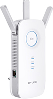
TP-Link RE455 v1
The TP-Link RE455 is a wall-pluggable dual-band wireless range extender (802.11b/g/n and 802.11a/n/ac) with Gigabit ethernet port. Advertised as 1750 Mbps (450Mbps for 2.4GHz and 1300Mbps for 5GHz).
Supported Versions
Experimental Versions
None at this time.
Hardware Highlights
Installation
Flash Layout

Please check out the article Flash layout. It contains examples and explanations that describe how to document the flash layout.
OEM easy installation
Simply apply factory image in OEM firmware web-gui.
OEM installation using the TFTP method
Specific values needed for tftp

| Bootloader tftp server IPv4 address | FILL-IN |
|---|---|
| Bootloader MAC address (special) | FILL-IN |
| Firmware tftp image | Latest OpenWrt release (NOTE: Name must contain “tftp”) |
| TFTP transfer window | FILL-IN seconds |
| TFTP window start | approximately FILL-IN seconds after power on |
| TFTP client required IP address | FILL-IN |
Upgrading OpenWrt

LuCI Web Upgrade Process
- Browse to
http://192.168.1.1/cgi-bin/luci/mini/system/upgrade/LuCI Upgrade URL - Upload image file for sysupgrade to LuCI
- Wait for reboot
Terminal Upgrade Process
If you don't have a GUI (LuCI) available, you can alternatively upgrade via the command line. There are two command line methods for upgrading:
sysupgrademtd
Note: It is important that you put the firmware image into the ramdisk (/tmp) before you start flashing.
sysupgrade
- Login as root via SSH on 192.168.1.1, then enter the following commands:
cd /tmp
wget http://downloads.openwrt.org/snapshots/trunk/XXX/xxx.abc
sysupgrade /tmp/xxx.abc
mtd
If sysupgrade does not support this router, use mtd.
- Login as root via SSH on 192.168.1.1, then enter the following commands:
cd /tmp
wget http://downloads.openwrt.org/snapshots/trunk/XXX/xxx.abc
mtd write /tmp/xxx.abc linux && reboot
Debricking
→ generic.debrick Do not attempt to flash vendor firmware from LuCI, this will brick your device.
Failsafe mode
Basic configuration
→ Basic configuration After flashing, proceed with this.
Set up your Internet connection, configure wireless, configure USB port, etc.
Specific Configuration

Network interfaces
The default network configuration is:
| Interface Name | Description | Default configuration |
|---|---|---|
| br-lan | EXAMPLE LAN & WiFi | EXAMPLE 192.168.1.1/24 |
| vlan0 (eth0.0) | EXAMPLE LAN ports (1 to 4) | EXAMPLE None |
| vlan1 (eth0.1) | EXAMPLE WAN port | EXAMPLE DHCP |
| wl0 | EXAMPLE WiFi | EXAMPLE Disabled |
Switch Ports (for VLANs)

Numbers 0-3 are Ports 1-4 as labeled on the unit, number 4 is the Internet (WAN) on the unit, 5 is the internal connection to the router itself. Don't be fooled: Port 1 on the unit is number 3 when configuring VLANs. vlan0 = eth0.0, vlan1 = eth0.1 and so on.
| Port | Switch port |
|---|---|
| Internet (WAN) | EXAMPLE 4 |
| LAN 1 | EXAMPLE 3 |
| LAN 2 | EXAMPLE 2 |
| LAN 3 | EXAMPLE 1 |
| LAN 4 | EXAMPLE 0 |
Buttons
→ hardware.button on howto use and configure the hardware button(s). Here, we merely name the buttons, so we can use them in the above Howto.
The TP-Link RE455 has the following buttons:
| BUTTON | Event |
|---|---|
| Reset | reset |
| WPS | wps |
| LED On/Off | BTN_0 |
Hardware
Info
Photos
Front:
Insert photo of front of the casing
Back:
Insert photo of back of the casing
Backside label:
Insert photo of backside label
Opening the case
Note: This will void your warranty!
There are four screws in the back of this device. After unscrewing them, the front panel can be easily removed. (There is one clip in each side). The serial is in the front side, so if you just want it, it is enough. It is harder to remove the back case because the wiring to the antennas and the power plug.
Main PCB:
Insert photo of PCB
Serial
→ port.serial general information about the serial port, serial port cable, etc.
Note: Not tested!
Seems needs populate unmounted R64 & R69 with 0201 resistors/jumpers
Connect only GND, RX and TX, don't connect VCC (3v3)

| Serial connection parameters | 115200, 8N1 |
|---|
JTAG
→ port.jtag general information about the JTAG port, JTAG cable, etc.
How to connect to the JTAG Port of this specific device:
Insert photo of PCB with markings for JTAG port
Bootloader mods
Hardware mods
None so far.
Bootlogs
OEM bootlog
COPY HERE THE BOOTLOG WITH THE ORIGINAL FIRMWARE
OpenWrt bootlog
COPY HERE THE BOOTLOG ONCE OPENWRT IS INSTALLED AND RUNNING
Notes
Space for additional notes, links to forum threads or other resources.
- ...
Tags


